
The Galley
Categories
Tags
Recent articles
Ubuntu 16.10 LXC host on ZFS Root, with EFI and Time Machine
How to connect any serial device to the internet
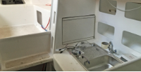
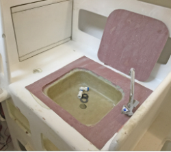
The Galley seems a bit of a grand name for the first 600mm inside the companionway hatch, but that's where the sink, hob and fridge are so it'll have to do. This will be a bit of a work-in-progress article as I get time to update
The Sink
 I bought a sink from
Aquafax and installed it.
I almost immediately regretted this - it used a lot of my precious counter-top space,
plus I did a crap
job of the install it and could never get a 3mm bend out of the back, which meant
vast amounts of
caulking. It's so bad I didn't take any photos, best I've got can be seen to the right
here (with closed
fridge behind it).
I bought a sink from
Aquafax and installed it.
I almost immediately regretted this - it used a lot of my precious counter-top space,
plus I did a crap
job of the install it and could never get a 3mm bend out of the back, which meant
vast amounts of
caulking. It's so bad I didn't take any photos, best I've got can be seen to the right
here (with closed
fridge behind it).
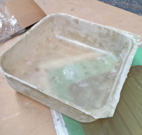 Eventually I came up with an idea for a replacement. I removed the old sink, sprayed
it with as much
mould-release as I could manage, then did a wet layup over the reverse-side of the
sink (so the sink
formed a male mould) with a few layers of epoxy-soaked glass tape. The advantage of
laying up over
the outside is that what would become the inside of my sink would be nice and smooth
where it was up against the metal.
Eventually I came up with an idea for a replacement. I removed the old sink, sprayed
it with as much
mould-release as I could manage, then did a wet layup over the reverse-side of the
sink (so the sink
formed a male mould) with a few layers of epoxy-soaked glass tape. The advantage of
laying up over
the outside is that what would become the inside of my sink would be nice and smooth
where it was up against the metal.
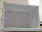
When dry, it turned out I hadn't used enough mould-release. In fact I'm not sure I could have - the fit was way too tight to remove the sink from the mould. Luckily fibreglass will flex quite a bit without breaking, so after a vast amount of effort and swearing I had the glass sink removed. I trimmed with a Dremel, filled with water, plugged the minor leaks with more tape and glass, then cut a hole for the plug. I'd used three layers of glass, and this gave a fairly rigid structure - probably about the same as the sheet-steel sink I was replacing.
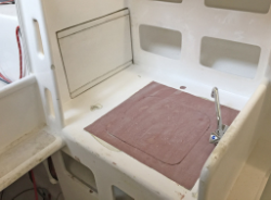
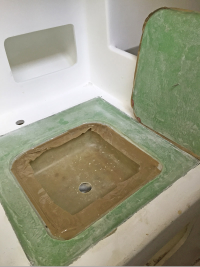 I still had the large hole in my worktop where I'd removed the old sink: more foam
and glass to the rescue!
I fabricated a flat panel and cut out the middle in the shape of the new bowl, before
taping and gluing
the bowl under this panel - the idea is I can put the cutout back in to cover the bowl.
I still had the large hole in my worktop where I'd removed the old sink: more foam
and glass to the rescue!
I fabricated a flat panel and cut out the middle in the shape of the new bowl, before
taping and gluing
the bowl under this panel - the idea is I can put the cutout back in to cover the bowl.
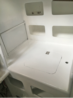
I then enlarged the hole in my worktop to fit this panel and fitted it in place. My goal was to have a flush surface over the entire worktop, but to be able to remove the panel to reveal the sink below. So I wrapped the cutout in a packaging tape "wall" to prevent epoxy from flowing between the sink cover and the rest of the panel; built a "ledge" out of packaging tape to prevent the epoxy from flowing into the sink bowl; then put the cutout back in and poured epoxy thickened with 407 low-density filler over the top of both the cutout and the worktop.
 The idea was the epoxy would self-level and I would sand it back to flush. Turned
out the boat
itself wasn't level, something I remedied hastily by jacking up the trailer. Fortunately
after an hour
or two I also thought to check to see how well the packaging tape was preventing the
epoxy from bonding
between the sink and the cover. It wasn't! A bit of heaving and I managed to get the
cover free - actually
I timed it perfectly, the epoxy had stopped flowing but wasn't set, so what had drained
into the sink
(my packaging-tape ledge had failed) was easy to remove with a paint-scraper. An hour
later and I would
have had a permanent bond, which would have been pretty stupid.
The idea was the epoxy would self-level and I would sand it back to flush. Turned
out the boat
itself wasn't level, something I remedied hastily by jacking up the trailer. Fortunately
after an hour
or two I also thought to check to see how well the packaging tape was preventing the
epoxy from bonding
between the sink and the cover. It wasn't! A bit of heaving and I managed to get the
cover free - actually
I timed it perfectly, the epoxy had stopped flowing but wasn't set, so what had drained
into the sink
(my packaging-tape ledge had failed) was easy to remove with a paint-scraper. An hour
later and I would
have had a permanent bond, which would have been pretty stupid.
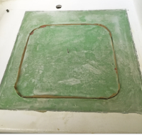
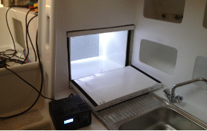
 A vast amount of sanding later and I'm extremely pleased with the results. First,
it's a few kg lighter
than the steel original. It's completely flush with the rest of the worktop, and the
bowl itself is
quite rigid now it's been bonded to the panel. The cover was a fairly rough fit at
first, but I've filled
the gaps so there's now a 1-2mm gap where it fits into the panel. The end result is
a 700x600mm flat
surface I can use as a chart table, with a sink underneath. The taps were moved from
the back to the
side - necessary now the sink is permanently bonded to the worktop, as the back of
the sink is
inaccessible.
A vast amount of sanding later and I'm extremely pleased with the results. First,
it's a few kg lighter
than the steel original. It's completely flush with the rest of the worktop, and the
bowl itself is
quite rigid now it's been bonded to the panel. The cover was a fairly rough fit at
first, but I've filled
the gaps so there's now a 1-2mm gap where it fits into the panel. The end result is
a 700x600mm flat
surface I can use as a chart table, with a sink underneath. The taps were moved from
the back to the
side - necessary now the sink is permanently bonded to the worktop, as the back of
the sink is
inaccessible.
Of course this would have all been a lot easier if I hadn't put the old sink in the first place, but as you can tell I am making this up as I go along so I don't feel too bad about it. Now I just need to figure out what sort of paint you use inside a sink... bilge paint I guess. Comments welcome.
Postscript 20 Mar 2016
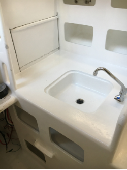 What sort of paint?
Two part epoxy, of course.
Looks good too.
The Fridge
The fridge was the first thing I had a go at constructing - it's a non-critical system so suitable for learning about fibreglass. Consequently I built and discarded a couple of cool-boxes which are undocumented - discarded because I hadn't really thought through how the door would work before I started construction.
I'd bought this book to guide me, but ultimately didn't really use it as the design is pretty simple: for a small boat fridge the bare minimum you need will be:
- An insulated cool-box
- An evaporator plate, which goes in your box. I used the Frigoboat E50881, which was the smallest one I could find but now seems to be out of production. The plate comes with quite flexible metal pipes pre-filled with refrigerant and with no-leak values on the end that fit to the compressor.
- A compressor. There are many options but most of them seem to use the venerable Danfoss BD35 compressor. This seems to be everywhere (a mate who works for Danfoss tells me they're often hooked up to a car battery and a solar panel in Africa to keep medicine cool). After a conversation with some guys from Penguin Frigo at a boat show, I bought the Frigoboat FM100 which was the cheapest, simplest way to get one - although I'm not sure what Frigoboat added to the BD35 to enhance it.
The Fridge Box
 Next timer you visit a shiny production boat, open the fridge and tap the inside of
it. Chances are it's
hollow - there's no insulation surrounding the fridge box, which is why whenever I've
chartered, the
fridge can only be on for a few hours without draining the battery. How well a cool
box stays cool depends
on the grade (R-value in the US, u-value in the UK) and thickness of the
insulation, but mine is a small
boat and two inches of insulation would leave me very little space for beer in the
fridge. Not good. Not
good at all.
Next timer you visit a shiny production boat, open the fridge and tap the inside of
it. Chances are it's
hollow - there's no insulation surrounding the fridge box, which is why whenever I've
chartered, the
fridge can only be on for a few hours without draining the battery. How well a cool
box stays cool depends
on the grade (R-value in the US, u-value in the UK) and thickness of the
insulation, but mine is a small
boat and two inches of insulation would leave me very little space for beer in the
fridge. Not good. Not
good at all.
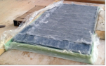
 So I bought a 6x1.45m offcut of 10mm
Aerogel Blanket from
Acoustiblok
here in the UK. At £45/m² this was a big investment, but I only needed a one meter
length so will sell
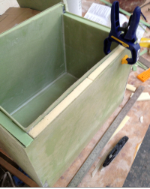
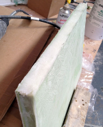
the rest when done. I built a roughly 600x400x400mm cube, open on one side in 3mm
foam with glass on the outside,
and a smaller one with glass on the inside. I nested the smaller one inside the larger
and packed the
gap between them with two layers (20mm) of Aerogel blanket before gluing in some foam
offcuts.
I did the same with a flat panel to form a door, and the end result is an insulated
cube with 26mm
thick walls and a hinged door.
So I bought a 6x1.45m offcut of 10mm
Aerogel Blanket from
Acoustiblok
here in the UK. At £45/m² this was a big investment, but I only needed a one meter
length so will sell
the rest when done. I built a roughly 600x400x400mm cube, open on one side in 3mm
foam with glass on the outside,
and a smaller one with glass on the inside. I nested the smaller one inside the larger
and packed the
gap between them with two layers (20mm) of Aerogel blanket before gluing in some foam
offcuts.
I did the same with a flat panel to form a door, and the end result is an insulated
cube with 26mm
thick walls and a hinged door.
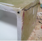
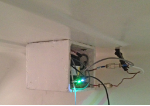
Some top tips if you try this approach: Aerogel blanket is impossible to drill through, so work out where the pipework from the evaporator plate to the compressor is going to be and use regular foam for the filler at that point. And figure out how your door is going to work before you build the box: careful inspection of these photos will show I did some surgery to the box to change the door surround before I installed it. I also glued on a layer of 3mm neoprene around the door to reduce heat loss, and fitted a plastic catch to hold the door shut when closed.
The Fridge Compressor
 The control unit for the BD35 compressor is designated 101N0210 by Danfoss, and it has 8 standard 6.3mm tabs, labelled:
- - incoming ground supply for the compressor
- + incoming 12 or 24v supply for the compressor and control unit
- + 12V always-on outgoing feed for the fan - always 12V, even if input is 24V.
- F this is switched to ground to turn the fan on. I'm not using this pin (I control the fan elsewhere) but I think it comes on when the compressor is on
- D is for "diagnostic" - when an error condition occurs, it is switched to ground to flash a diode. I presume a current-limiting resistor is part of this circuit
- C this is a the low-side of the "thermostat" circuit for the fridge, and is pinned to ground
- P a resistor can be placed between this and C to adjust the voltage at which the fridge automatically cuts out due to low-battery. I don't use this functionality so it's untested.
- T this is the high side of the "thermostat" circuit, and it's pulled up to 5V. Switching this to ground will turn on the compressor. The documentation supplied shows a mechanical switch between C and T and I'm unclear how much current flows when this is closed. I used a low Rdson SOT-23 MOSFET with drain connected to T and source connected to C - it works just fine, although be advised if you use a MOSFET switch and switch the wires accidentally, your compressor will be on permanently. I can confirm you can freeze a can of coke solid if you do this.
 You could do everything you needed with a mechanical thermostat switch and some wire,
but I can never
resist an opportunity to overcomplicate something so knocked up this circuit, which features:
You could do everything you needed with a mechanical thermostat switch and some wire,
but I can never
resist an opportunity to overcomplicate something so knocked up this circuit, which features:
- A connection for a thermistor to monitor the temperature inside the fridge - no mechanical thermostat here
- A connection for a reed-switch to determine when the fridge door is open - I drilled a hole for this in the fridge box and epoxied it into place, with the corresponding magnet glued into the door.
- A switched connection for a 12V LED strip to light up inside the fridge when the door is open - overkill for a 0.1m³ fridge, but a fridge without a door light just seems wrong.
- A buzzer that sounds if the door is left open (see previous point).
- A connector for a 12V computer fan - the original FM100 came with a whiney little 60mm fan, which I replaced with a nice quiet 120mm fan - four times as effective, a quarter of the noise.
- A 7-segment display and a couple of buttons to show/set the temperature
- A USB connection to program the chip and, if necessary, monitor the performance. This is more a side-effect of my favoured microcontroller than necessary functionality, but I've found that having a USB-connected fridge does make for a mildly amusing anecdote at parties.
It's not a particularly challenging circuit and not one of my best, but can be downloaded here if you're interested. Functionality is dead-simple: monitor the temperature (via the ADC) and the door switch, and turn the compressor, lights, fan and buzzer on and off as appropriate. The circuit itself is a small custom board powered by my go-to chip, the ATmega32U4. This is the core of the Arduino Leonardo and Teensy 2.0 - you could, theoretically, implement this circuit on a breadboard with one of those at the centre: with the exception of the 7-segment LCD display there's nothing except a few resistors, transistors and an LDO to drop the 12V power supply down to 5V to run the chip. The firmware as supplied would probably compile for the Arduino with no, or at least very few changes.
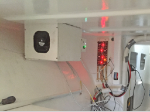
The compressor was put in a butt-ugly box (my first laminating effort, don't laugh) which I bolted under the cockpit floor, in the crawlway between the main cabin and the rear cabin. I've seen production boats (and, for that matter, hotel rooms) where the compressor is in the same unventilated area as the fridge - don't do this, the laws of thermodynamics will be against you. Just before painting I'll fill the gap between the fridge and the compartment to fit it semi-permanently.
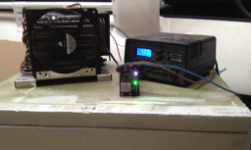
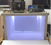 For refrigeration nerds only, here are some more pictures of the setup during testing.
My battery is
currently down so no fridge, but when I'm back online I'll update this article with
some diagnostics
so we can see how effective my Aerogel blanket is at keeping things cool.
For refrigeration nerds only, here are some more pictures of the setup during testing.
My battery is
currently down so no fridge, but when I'm back online I'll update this article with
some diagnostics
so we can see how effective my Aerogel blanket is at keeping things cool.
To be continued...