
Four serial ports on an ATmega32U4
Categories
Tags
Recent articles
Ubuntu 16.10 LXC host on ZFS Root, with EFI and Time Machine
How to connect any serial device to the internet
The ATmega32U4 chip (which underlies the Teensy 2.0, the Arduino Leonardo and Arduino Micro) has a USB serial port and a single hardware USART. If you want to use any one of the 40-odd other pins for serial communications, you have two choices:
First, SoftwareSerial, which allows any port
to be used but uses the delay method to control timing - essentially your CPU is put into a
busy loop, which makes simultaneous receive from multiple port impossible. Counter-intuitively
this makes
performance worse at low baud rates, as the delay is longer.
The other alternative is Paul Stoffregen's AltSoftSerial, which uses interrupts and so is limited to a single pin.
For high-speed data reception I understand that this is a complex task, but you can't tell me my 16Mhz chip is unable to read from two 4800 baud devices simultaneously. Fixing this appeared to be an easy problem but ended up taking me a whole day to diagnose with an oscilloscope, so I thought it worth documenting.
The results are a I have four ports on my ATmega32U4 - USB Serial, a 38400 baud hardware serial and two 4800 baud ports, all of which can transmit and receive simultaneously. No delay loop. The catch is the CPU is constantly busy (so what) and it only works at lower baud rates - the practical ceiling is limited by whatever else you're doing, but for me (various combinations of reading from one port and relaying to another) I think my practical ceiling is about 19200 baud overall, which could be made of 4 x 4800 baud, or 2 x 9600, or so on.
The trick is to avoid the problem of exact timing by simply sampling the pin as often as you can over the period of one bit - 208us for 4800 baud - and taking the average. If it's high more than it's low, it's a one rather than a zero. My code is taking about 18us per loop iteration, which is 11 samples per bit. So something like this called on every pass through loop():
      #define PINISHIGH  (PINB & (1<<PB0))      // anything that's non-zero if pin is 1
      #define BAUDUS 208                        // microseconds per bit - 1000000 / 4800 = 208
      volatile uint16_t bitstart;               // Timestamp when this bit started
      volatile uint8_t bitcount;                // Number of bits to read
      uint16_t highcount, loopcount;            // Number of high samples and total samples for this bit

      if (bitcount > 0) {
          uint16_t now = micros();
          rxloop++;
          if (PINISHIGH) {
              rxhigh++;
          }
          if (now - bitstart > BAUDUS) {        // enough time for one bit has passed
              bitstart += BAUDUS;
              rxbyte >>= 1;                     // bytes are filled LSB first
              if (rxhigh << 1 > rxloop) {       // bit is high, on average
                  rxbyte |= 128;
              }
              if (!--bitcount) {                // We've read 9 bits - start bit plus 8 data bits.
                  rxbuf[rxbuftail++] = rxbyte;  // Handle the new byte (I just push it to a buffer)
                  rxbyte = 0;                   // and prepare for next one.
              }
              rxloop = rxhigh = 0;
          }
      }
This code is quick to run. However it's only part of the solution - the baud rate will tend to drift over time, and the transmitting device might not be exact. We need to alter our timing to match the changes to the pin - we can do this in an interrupt (either a pin change interrupt, or one of INT0, INT1, INT3 or INT6. That's a total of 10 pints to choose from for Rx. Put this in the interrupt routine, to be called whenever the pin changes:
        uint16_t now = micros();
        if (bitcount == 0) {    // This pinchange is the start bit of a new byte
            bitstart = now;
            bitcount = 9;
        } else {
            bitstart = now - bitstart > BAUDUS/2 ? now - BAUDUS : now;
        }
This will adjust the timer every time the pin is changed, pulling it forward or back depending on whether the pin change is closer to the start or the end of our expected cycle. In practice I lose a few (edit: quite a few) NMEA0183 sentences to line-noise, but it's well within acceptable levels. It only works for 8-N-1 as well, but I haven't seen anything else since the mid 1980's so I think this is acceptable.
What's it good for
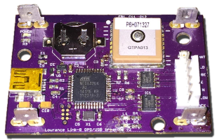 I have a VHF which
takes an external signal from an NMEA0183 GPS, and outputs AIS messages at 38400 baud,
as well as other messages at 4800. My board has a GPS receiver, which is relayed to
the VHF and to USB.
The VHF responses (at both 4800 and 38400 baud) are relayed to USB as well. All of
these can be
rerouted or turned on/off if necessary, and instead of an external GPS and two RS422
to USB converters,
I have one small board that does everything I need. It even monitors the backup battery
voltage for
the GPS!
I have a VHF which
takes an external signal from an NMEA0183 GPS, and outputs AIS messages at 38400 baud,
as well as other messages at 4800. My board has a GPS receiver, which is relayed to
the VHF and to USB.
The VHF responses (at both 4800 and 38400 baud) are relayed to USB as well. All of
these can be
rerouted or turned on/off if necessary, and instead of an external GPS and two RS422
to USB converters,
I have one small board that does everything I need. It even monitors the backup battery
voltage for
the GPS!
Why bother? You wouldn't ask that if you'd seen my wiring loom. Replacing 3 NMEA cables, two RS422 converters, two USB cables and an external GPS with one board and one USB cable is a definite win.