
LiFePo4 battery
Categories
Tags
Recent articles
Ubuntu 16.10 LXC host on ZFS Root, with EFI and Time Machine
How to connect any serial device to the internet
This article is turning into a bit of a long story. It was originally published on 31st March 2015, but there are lots of updates since then. Check the bottom for new content. Latest update is 7th September 2015
Part of the fun here is playing with new technologies, which includes Lithium Batteries. As any fule know those are the ones that explode, are horrendously expensive and whose performance doesn't live up to their advertising.
There are those better qualified to cover the theory: here's an excellent article which I found after I'd already ordered the cells, which pleased me a lot as he has more knowledge than me and came to the same conclusions.
So no theory from me, just installation details. My goal is a combined starter/house battery for a small-but-electrically-intense boat with an outboard motor equipped with an alternator. The outboard changes the game a bit because a) I can use one battery - if it goes flat, I'll use the pull cord, and b) the alternator will always be running when the motor is running. This has implications for LiFePo4 batteries, which don't like being overcharged.
First some conclusions:
And if you still need convincing, take a look at these numbers:
| Lifeline GPL-4DL | CALB Cam 72 x 8 | |
|---|---|---|
| Nominal Voltage | 12V | 12.8V |
| Listed Capacity | 210Ah | 144Ah |
| Available Capacity (max lifetime) | 105Ah (50% DOD)1 | 100Ah (70% DOD) |
| Charge Cycles (max lifetime) | 1000 | 50002 |
| Available Capacity (max power) | 158Ah (80% DOD) | 115Ah (80%) |
| Charge Cycles (max power) | 550 | 30002 |
| 100% Discharge? | No | 91% capacity after 290 cycles |
| Self Discharge | 2% / month | 04 |
| Can be stored discharged? | No | Yes |
| Weight | 56kg | 16kg |
| Volume | 25 litres | 7 litres |
| Size (HxWxD) | 220x220x527mm | 218x135x240mm |
| Cost3 | €604 | €710 |
- Lifeline recommend 50% DOD for max lifetime, and not more than 80%. I have a feeling the lifetime figures might be quite optimistic as Odyssey claim "up to 400 cycles when discharged to 80% DOD" for their AGM batteries.
- EVTV have tested these cells extensively, and here is a manufacturer datasheet. This lists >= 2000 cycles, I'm taking the figures from EVTV because they're from testing, whereas manufacturer datasheets are generally rubbish
- Pricing in € because that's what I paid in. Price for the LiFePo4 cells includes the BMS and Contactor, as I consider these essential. Pricing for the Lifeline battery sourced from here. Both exclude VAT and shipping and prices from around October 2014.
- OK, no self-discharge on the cells but if you have a battery management system that will draw power - I'm budgeting about 20ma, which is about 0.4%/month for this size of pack. For long term storage you'd disconnect this.
So what's my setup? My shopping list is below. A few of my purchasing decisions were based on a presumed 100A maximum current draw - this will be when using the electric start on the outboard. Finding actual measured figures on this is almost impossible - the Yamaha 9.9HP owners manual lists the "minimum marine cranking amps" as 323A, which is obviously not the current that will be drawn from the battery otherwise the cables would be the size of your arm. Best I could find was a the starter for a 9.9HP Evinrude being measured at 32A, and a Mariner 175HP measured at 150A. So 100A ought to do it.
-
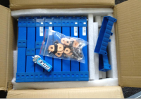
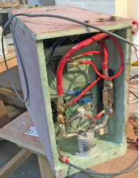
 8 x Calb CAM72 cells, in a "4S2P" installation - 4 sets of 2 parallel cells, wired
in series.
Each cell is rated at 3.2V with a 72Ah capacity, so I get 12.8V (give or take) and
144Ah.
Cost per cell is about €75 per cell, although inevitably that will vary. The cells
came with a
plastic outer case and a cover over the terminals, and the case was bolted to hold
the cells
firmly together.
8 x Calb CAM72 cells, in a "4S2P" installation - 4 sets of 2 parallel cells, wired
in series.
Each cell is rated at 3.2V with a 72Ah capacity, so I get 12.8V (give or take) and
144Ah.
Cost per cell is about €75 per cell, although inevitably that will vary. The cells
came with a
plastic outer case and a cover over the terminals, and the case was bolted to hold
the cells
firmly together.
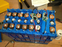
- Enough bus-bars to connect them - 8 came with the cells, I need 11 in total.
- A pile of M6 Nordlock washers. These were written up elsewhere, they're new to me but look useful when you absolutely, positively do not want your bolts to shake loose.
- A battery management system. I went with the HousePower BMC, because it was relatively cheap, simple, and I could understand it. It's sole purpose is to cut power to the battery when the voltage is too high or too low - nothing else. You'll need 4 x cell boards (remove the fixed ring and solder on a wire for both the +ve and -ve connections, terminated with a crimped 6.2mm ring connector). Total cost was about USD$125.
- A mains charger. I struggled to find one designed to work with LiFePo4, as opposed to just an "also works with Lithium" sticker. Although charging LiFePo4 is actually simpler on paper than lead acid - none of that bulk, absorption, float bollocks, just cut off at a certain voltage - ironically you're going to pay more for it. The Sterling Power PCU1220 delivers 20A and has a configurable cut-off voltage, which is good as its standard LiFePo4 profile cuts out at 14.6V. This is 3.65V/cell, the same as the "alert" level in the BMS, which means the battery cutoff would constantly be tripping. So while it's useful for the initial balance, I'll be running a custom profile at 14.2V when installed to ensure the alarm won't trip. For these features I paid £269, which seems like a good investment.
- Accessories for the Battery Management System. In my case, this is a Tyco Kilovac LEV100 "Contactor" (as best as I can tell, just posh name for a big relay) for £10 on eBay - some standard automotive relays, a DPST switch (this will carry minimal current which compares nicely to the whacking great battery isolation switch you'd normally have to install for lead acid), a pushbutton, and (for testing) a 12V buzzer and the end of a 12V LED strip, wired into the high-voltage alarm circuit on the BMS.
- A desktop PSU. This is an essential item for the initial balance, which is an equally essential step that has to be done, although probably only once. I bought a "Tenma 72-10480" on eBay for about £40, which will put out 3A - enough if you're not in a hurry.
- A last-resort fuse. Everyone seems to recommend "Class T" fuses, but I couldn't find one under 200A. I want to blow at 100A so got a 100A ANL fuse. Remember to spend time laughing at the "display fuses cases" for these on eBay, as they're apparently used by the lads who beef up their car stereos - "phwoar, look at my big shiny fuse". I bought a Blue-Sea 5005 holder because it was made of a plastic that won't melt when things go wrong (unlike most of the boy-racer products), and some Blue-Sea fuses as they're ignition protected - i.e. they won't catch fire when they blow. Both more expensive than I would have imagined, the fuses alone are about £12 each from Aquafax.
- Cabling accessories - some 25mm² tinned copper cable, some 6mm and 8mm lugs and a Hydraulic Crimper. Hydraulic things are cool, and at £25? That's about the same as 1m of cable. Bargain.
Down the line this will be added to:
 And here's the process.
Conclusions at time of publishing
So far, none. It's been wired in since about end of February 2015 and is taking charge from the mains charger and delivering power on demand. It's shut down when unattended at low voltage (before I put the charger in, and I left it running the main computer on the boat for about a week) and at high voltage (when I set the charger to 14.4V rather than 14.2V), and both times I came in to find the battery alarm on and everything disconnected as required.
However I don't have any proper measurement of charge status yet, or any long-term figures. I haven't hooked it into an alternator or solar for charging, and the most I've tapped it for is about 10A: I need to test starting the engine, which means buying an engine. So these tests will come over time, and I'll update this page when it does.
Followup 1: 5th July 2015
My battery controller has packed up. I'm a bit annoyed about this, it suddenly started going haywire with the main contactor flicking on and off rapidly. It could be a bad connection somewhere, but I couldn't identify where visually or with a multimeter. I'm also not terribly impressed with the design of the system - I remember a joke in Readers Digest as a kid about a car with a single red warning light in the middle of the dashboard, explaining that the experienced driver will normally know what is wrong. I didn't find this very funny then and I still don't now - there is no diagnostic information coming out of this board other than a buzzer. Inevitably I have designed a replacement system which has the key features I want - integrated coulomb counting, complete configurability of all levels and thresholds, and a USB interface. I'm ironing out the kinks but it's looking good so far. Will document it once it's had a few months shake down.
Followup 2: 14th August 2015
 My new battery management system went in yesterday and is finally working, although
with caveats.
The design above needs revision.
My new battery management system went in yesterday and is finally working, although
with caveats.
The design above needs revision.
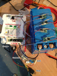
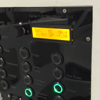
On the plus side, my BMS talks over USB so I can easily hook it into my computer as you can see above. This was before I'd measured the battery state of charge, which is why it's 0%. The power through the shunt is measured at about 8000hz, so I can very accurately count coulombs to record the state of charge.
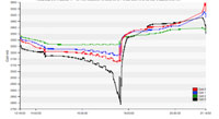 It's also talking to the cell management boards so I can measure cell voltage and
temperature. This
turns out to be very important as it will tell me which cell is playing up and whether
the system
is properly balanced. Turns out it's not - see the graph on the right.
Hooray for raw data!
It's also talking to the cell management boards so I can measure cell voltage and
temperature. This
turns out to be very important as it will tell me which cell is playing up and whether
the system
is properly balanced. Turns out it's not - see the graph on the right.
Hooray for raw data!
I hope this will partially explain why when I measured a full charge/discharge cycle on the battery I got about 76AH, which is way too low. Missing the 0.5A for the contactor as described above will throw this off by another 5%, so for now take that measurement with a large pinch of salt.
Followup 3: 7th September 2015
Last week we turned over the engine for the first time. The Yamaha 9.9 has a 600W starter motor (50A at 12V), so if we assume a large margin for losses in the process, turning the motor over drew probably in the region of 60 - 70A. We only ran the starter for a few seconds to verify the wiring and measure the current (inconclusive due to setup errors as it turned out).
A week later the battery was dead, and although the Battery Management System I'd designed would have informed me of this, ****ing British ****ing Telecom had seen fit to pull the plug out of my internet connection at the build site then make me wait two weeks for them to fix it. So no idea when or at what voltage the battery shut down. On inspection I found one - just one - of the 8 cells had dropped to 2.4V, which should be impossible as a) this is below the minimum voltage at which the management system would have shut down, and b) the cells are wired in four sets of two pairs, with each parallel pair having the same voltage. The cell was one of the two that made up "Cell 3" in the PDF in my last report, which was the one that triggered the low voltage during discharge.
I'll skip the process of how we got there, but here's what we think happened.
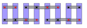
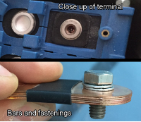
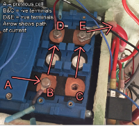 First the setup. Each cell has a positive and negative terminal, 12mm in diameter
and tapped with an M6
thread, and made of aluminium. On top of these terminals are rigid copper bars 2.5mm
thick which link both the
two cells in the pair and the sequence of four pairs; the center of each bar has a
thin (<1mm) layer of
insulation. The bars are fastened to the battery terminals with an M6 machine screw
in A2 steel, locked
tight with a Nordlock washer - I think these are steel with a zinc protective coating.
When I set the cells up, I bolted them together in pairs, gave each pair an initial
full charge, and
they've been paired ever since.
First the setup. Each cell has a positive and negative terminal, 12mm in diameter
and tapped with an M6
thread, and made of aluminium. On top of these terminals are rigid copper bars 2.5mm
thick which link both the
two cells in the pair and the sequence of four pairs; the center of each bar has a
thin (<1mm) layer of
insulation. The bars are fastened to the battery terminals with an M6 machine screw
in A2 steel, locked
tight with a Nordlock washer - I think these are steel with a zinc protective coating.
When I set the cells up, I bolted them together in pairs, gave each pair an initial
full charge, and
they've been paired ever since.
Despite being connected by thick copper bars, on measuring the pair I found one cell at 3340mV and one at 2460mV. It's clear the copper wasn't actually touching both the terminals of the cells in this pair - either as a result of some sort of thermal expansion and contraction due to the large load, perhaps a fraction of a mm shift in the cells as the battery moved around, or perhaps they had never touched at all.
 The copper bars are completely rigid and although they were bolted down firmly,
the layer of insulation in the middle along with the edge of the battery case could
have kept the copper
bar slightly suspended and prevented it from making a clean connection to the terminal.
The two
terminals would still have been connected through the steel bolt and the washer, and
we measured the
resistance of the washer at 10Ω, I suspect due to the coating. So there was some electrical
conductivitiy, but there should have been at least 100 times less resistance.
The copper bars are completely rigid and although they were bolted down firmly,
the layer of insulation in the middle along with the edge of the battery case could
have kept the copper
bar slightly suspended and prevented it from making a clean connection to the terminal.
The two
terminals would still have been connected through the steel bolt and the washer, and
we measured the
resistance of the washer at 10Ω, I suspect due to the coating. So there was some electrical
conductivitiy, but there should have been at least 100 times less resistance.
So what have we learned?
Quite a bit, as it turns out
What happens next?
Well, first, this pretty much rules out me getting on the water before winter, which is a pain in the arse. The reason is I now need a complete redesign of the battery system, as some other things came up during testing:
- A shunt isn't a very accurate way to measure current. After turning over the engine, the current draw on the system should have returned to its previous level, but was in fact showing itself to be about 2A different. I put this down to the change in resistance due to the heating of the shunt resistor - it's not good enough, so I'll be switching to an ACS756 hall-effect current sensor, which I've tested before with some sucess.
- The more reading I've done, the more I'm convinced constant cell balancing is a must, even for systems that are relatively lightly loaded like a house battery on a boat. LiFePo4 cell balancing is a field that is advancing every few months - there are now about a dozen different techniques I'm aware of. I'll be attempting to implement one of the best of these (a cell-to-cell balancer using a quasi resonant LC converter and boost converter, which is as complicated as it sounds), in the next design. This should result in very, very high efficiency during balancing.
- The rectifier on a Yamaha F9.9 is regulated - I was unclear on this, but bought the service manual and it looks like this is the case with any Yamaha outboard with electric start. Output is regulated at 13V regardless of engine speed, which is 3250mV per cell. This means the engine alternator will be able to prevent the battery from going completely flat, but will not be able to add any significant charge to the battery at all. If I'm to charge the batteries to above about 25% while at sea, I will have to use something else: solar, wind, towed impeller or methanol. Solar was always on the cards, but I was putting it off - no longer an option.
All up, a bit of a shit week, but finally accepting I'm going to miss the water this year might allow me to slack off the pace a little.