
The Engine
Categories
Tags
Recent articles
Ubuntu 16.10 LXC host on ZFS Root, with EFI and Time Machine
How to connect any serial device to the internet
I have a shiny new Yamaha 9.9 LEX. This is the extra-long-shaft model (25") and has electric start. It came with the 703 control box. This is apparently the standard control box, largely unchanged for about 20 years, and combines the throttle and gear shift lever with the electrics to start it.
Replacing the Yamaha 703 with a flush-mounted plate
This is a Yamaha 703 control unit. Slightly older model than mine, but close enough.
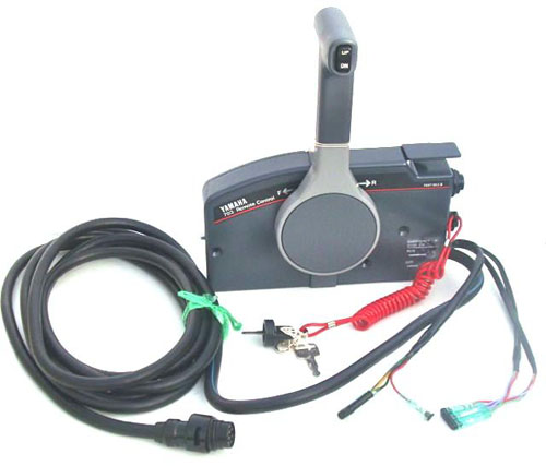
The 703 is a big unit and I have a small cockpit. Plus routing the cables and control wires to it in a useful way was going to be a bit of a mission.
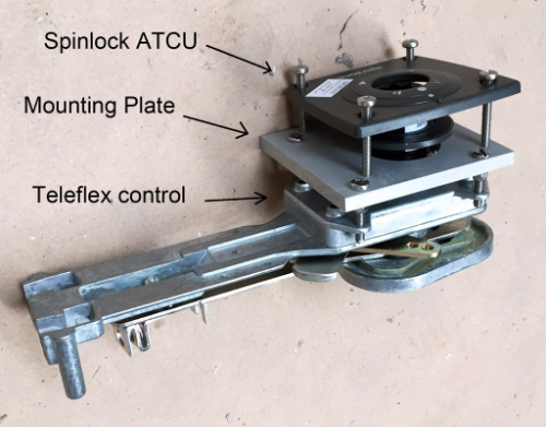
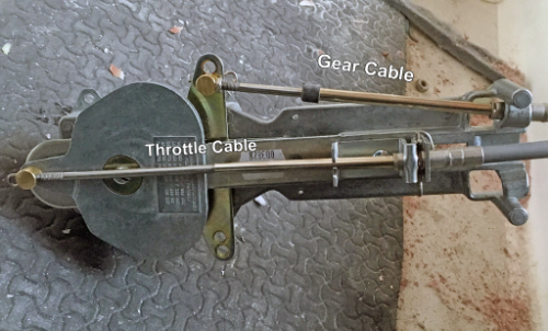
A post on the F-Boat forum mentioned an after-market replacement for the mechanical side of things, so I searched and found the Spinlock ATCU, a faceplate designed to fit over a "Teleflex Throttle", whatever that is. I'm not much of an engine person, but apparently these are so well known as to be almost generic. I eventually found them, they're now known as Seastar Solutions, and although none of the models listed on the Spinlock Website matched, I figured out that what I wanted was the 700 SS, although it seems to go by about a dozen different names, including 700SS, B700, CH2100P, TX172103, maybe TX172152 - not sure on that one.
Eventually I gave up trying to find the right part just took a punt on what looked right from Force 4 buying the the Spinlock plate at the same time - the theory being if I bought them together I could send them back if they didn't fit. If I'm honest, I'm still not entirely sure of the product code I bought (edit 20160626 - it's a TX172103).
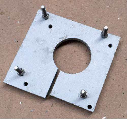
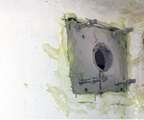
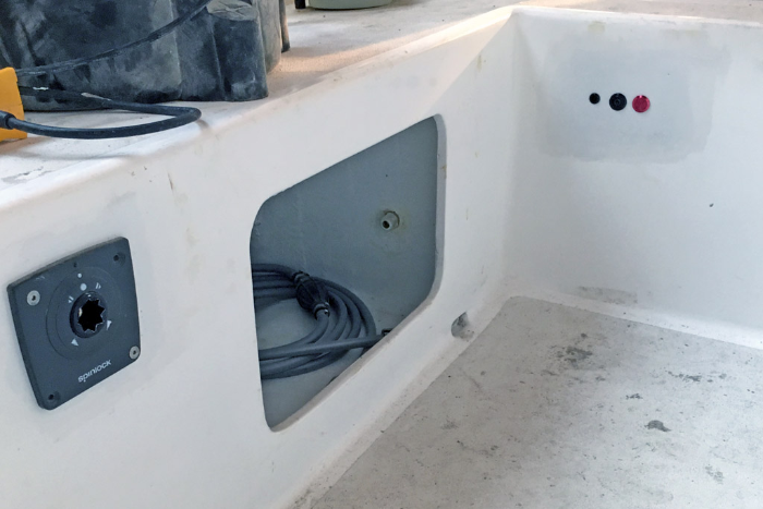
It all fitted together - I threw away the faceplate and lever that came with the Teleflex unit. I also made up a mounting plate from some scrap aluminium which I epoxied in place in the side of the starboard cockpit seat (if you're considering the same, here is the SVG outline of the plate).
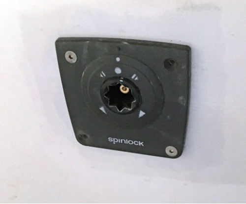
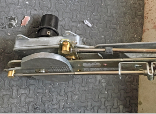
The control itself is very clunky compared to the Yamaha original, and using a winch handle as a lever doesn't really work: the handle is too long and pushes the shifter into neutral too easily. I gave in and bough the dedicated lever from Spinlock, which improved things bit.
Overall, the mechanical linkage is pretty rubbish compared to the original. But, it is tucked out of the way. I'll try it out, and if I really hate it I still have the original unit.
Replacing the Yamaha 703 electrics
 The electrical cable running into the 703 is about 15mm Ø, and carries ten wires.
Fortunately,
given how standard the 703 is, the wiring is pretty well documented. I experimented
with a
multimeter and these were my notes:
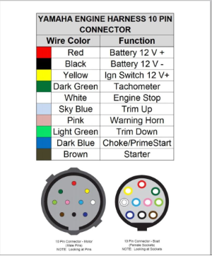
The electrical cable running into the 703 is about 15mm Ø, and carries ten wires.
Fortunately,
given how standard the 703 is, the wiring is pretty well documented. I experimented
with a
multimeter and these were my notes:
- White: switch to black to kill engine, float to run (into engine kill switch). Note pulling this to ground is the only way to stop a running engine.
- Brown: from key through engine neutral switch (closed when in neutral) to engine for ignition. Raise to +12V to start
- Pink: switched to ground by engine to sound alarm
- Yellow: turn key on to connect to red
- Red: +12V, always
- Black: Ground, always
- Dark Green: tacho, purpose unclear (note: this is wired directly to the unregulated alternator output from the engine, and puts out an AC signal of maybe +/- 12V, or maybe up to about +/- 80V. I'm not sure).
- Light Blue: not used (note: this is for engine trim, which I don't have)
- Light Green: not used (note: this is for engine trim, which I don't have)
- Dark Blue: Choke. Push key in to connect to Yellow
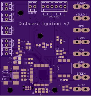
What could go wrong? I cut the wires and knocked up this circuit, which you can download here. It's pretty simple, and replaces the key with three buttons: power on, ignition, and choke. There's also a switch to override the "throttle in neutral" check, important as I don't have a "throttle in neutral" microswitch fitted to the Teleflex unit. (Edit 20160905 - I wasn't sure of the part number for this, but it's a "Teleflex 178000". Available from a local chandlery for £25, the kit appears to be some connectors, two machine screws and a single "XGG2-88Z1" microswitch, available from a local electronics wholesaler for £2.33. How I love marine pricing.
Everything is switched manually (ok, via a MOSFET) - I don't want to be debugging the software as I drift onto a lee shore. The only nod to the world of computers is that I can report on the status of the device back to the computer, including alarm state and engine RPM (untested), and I can electronically enable/disable the "kill switch". This allows me to disable the engine when I set the alarm on the boat, for instance. I can also detect if the engine is disconnected on the computer, which allows me to set off an alarm if someone tries to pinch it!
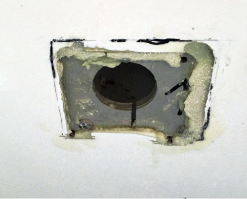
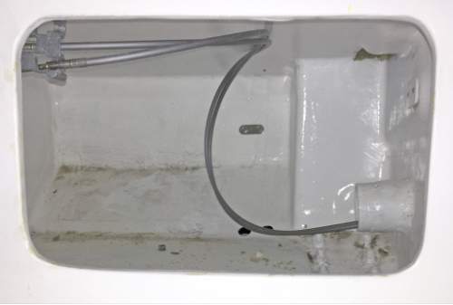
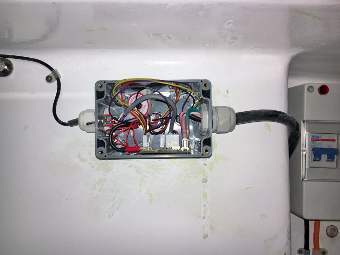
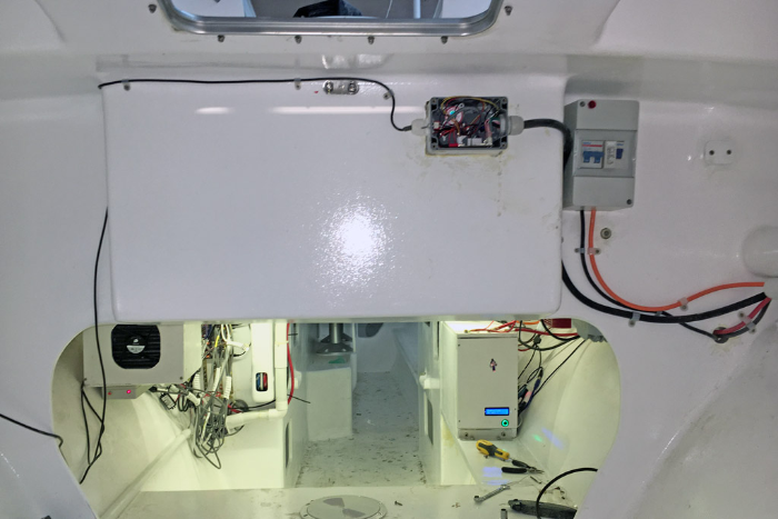
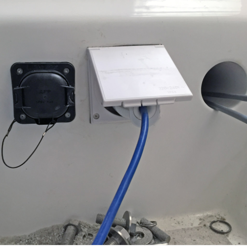
To mount, I cut a hole in the rear wall of the cockpit into the rear cabin, and epoxied in an IP65 rated box using West System G-Flex epoxy. I thought regular epoxy was bad: this stuff is vile, but it certainly sticks to plastic. Faired, painted, added some IP65 rated buttons and suitable IP65 cable glands on the rear, and it worked first time. The wiring all runs inside the rear cabin to the connector at the back of the boat.
Connecting it all to the engine
The last bit was actually hooking all this up to the engine. I have two mechanical cables (throttle and gear shift - these are "Teleflex Morse 33C" type cables), two 16mm² power cables and 8 x control wires of about 1.5mm², but I'd still like to to be able to remove the engine for security and maintenance with relative ease - something that would have been impossible with the original Yamaha 703 control box (edit: to clarify, although the control cable could be easily disconnected, the battery cables would need to be disconnected from under the engine cowl).
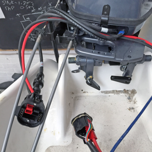
Imagine my surprise when this turned out to be possible, with something called an Andersen SPEC Pak. This kit includes Andersen Powerpole connectors for the high current wires (the one I bought is rated to 75A), plus a number of smaller-gauge auxiliary wires, all in one IP68 rated plug! It's a bit of a beast but was also pretty much the only game in town.
I ordered the following from Torberry in Portsmouth, UK:
- PP060-XXX - 75A Powerpole Pack (one each, read and black)
- PMODCNTPK#16 - Auxiliary Contact Pack, 16AWG
- SK9-076 - Mid Power SPEC Pak Receptacle
- SK2-076C04 - Mid Power SPEC Pak Panel Mount Receptacle Kit
- SK6-076C04 - Mid Power SPEC Pak Plug Shell Kit
- PS1T40-24X - Mid Power SPEC Pak Cable Gland
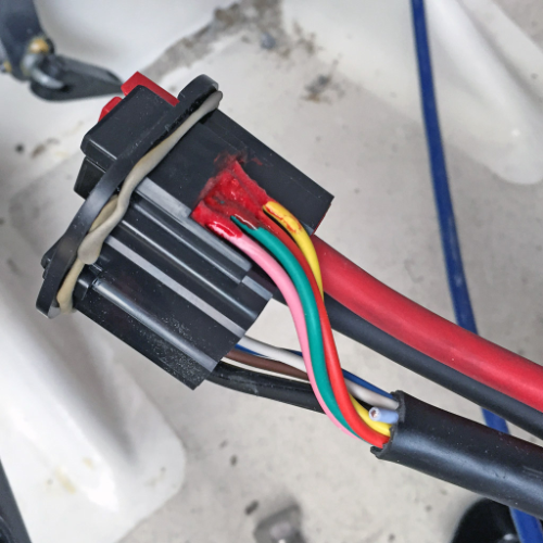
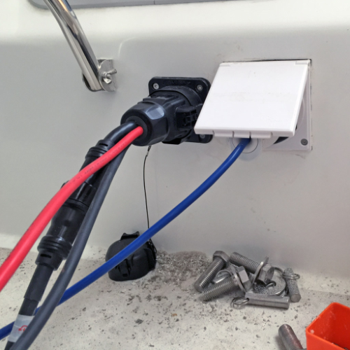
Assembly was a bit fiddly, and (perhaps due to some misalignment) the plug doesn't fit into the socket quite as easily as I'd hoped. I need to give it a good shove - I guess I'll find out if it stays connected in a seaway. To my surprise the wires on the Yamaha control cable were not tinned copper - this is a wet part of the boat, so I covered the connectors in liquid electrical tape before assembly, as I don't want them corroding. I also added some Butyl Rubber for sealing. This was a bad idea, and I think it contributed to my poor fit. Don't do this.
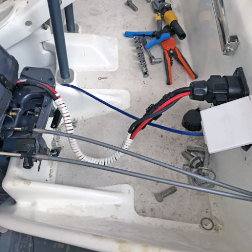
Some cable wrap was appropriated from the office, and I have a fairly neatly packaged connection to the engine.
I had two Andersen Powerpole connectors left over, so I crimped these to a stub of 16mm² cable with an M6 ring on the other end. This should make it easier to run the engine on a test rig.
Powering it up
It's important to limit the resistance in high-current wiring - an ohm or two makes no difference when you're moving around milliamps, but if you're moving 100A it's bad news. All connections introduce resistance, that's inevitable. So I sized the battery cables up to 16mm², and dipped them in some Noalox before crimping. The starter motor on the Yamaha 9.9LEX is rated at 600W, which is 50A at 12V, and making some allowance for transmission losses I'd sized everything to take 80A, give or take.
With the battery finally installed this week, I had the chance to turn over the engine and check these numbers. With the cylinders dry and the battery at 13.3V, the motor only drew 17A! No doubt this will go up once I fuel the engine and put it in the water, but I'm pretty confident everything is well within tolerance.
So now I have a working engine. But why stop there?
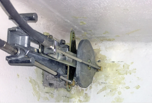
Outboard / Tiller Linkage
Another good idea I pinched from a comment on the F-Boat mailing list was linking the tiller and the engine. This should improve manoeuvrability a lot at low speed.
Searching for "outboard tiller linkage" threw up a few designs, which I left to fester in the back of my mind for few weeks. There were two convenient bolts holding the tiller to the rudder, and piggy-backing onto those would save me from having to drill any more holes. I did some prototyping and came up with this design:
I added a Raymarine M81105 rudder angle sensor too, because I'd got a good price on a used one. Overkill? Yes, I've heard of it. I had the bracket (PDF or DXF) fabricated in 2mm 316SS to fit over the existing bolts. The axle and pushrods are just M6 threaded rod coupled to some M6 clevis joints, again courtesy eBay. Before launching I'll grind the thread off the rods where not in use as the fittings tend to catch on the thread. The plate is 6mm Aluminium plate, anodised and bolted to the engine.
The plate is bolted in place, but the pushrod can be disconnected when I tilt the engine up - you just slide the pushrod up and over the "pin" (a bolt with the thread filed off) sticking up from the plate. I'm expecting weight and friction to keep it in place when in use, although this may need revising. I've added a torsion spring (not added in this video) to the clevis joint on the bracket, which swings the pushrod forward when not connected so it doesn't flop about. Will add some photos of this in the next update.
(Incidentally the main trouble with playing engineer is I don't know what any of these things are called, which makes them difficult to search for. Try describing a torsion spring in Google and see how far you get)
The rudder angle sensor is bolted to a piece of 3mm FR4, which I epoxied onto the conveniently located moulded outboard bracket. This can stay permanently connected to the tiller. It's just an expensive potentiometer, and the three wires are run up the pipe containing the gear/throttle cables, through a gland and into an extremely simple little circuit board which converts the analog values to an angle and reports it over USB to the computer.
All the metals except for the anodized aluminium plate and the torsion spring are 316 stainless steel, which is good because this is going to get WET!
Postscript 2016-09-05
The Teleflex 172103 is a nasty, finnicky piece of work. And my control box waterproofing was tested and found to be lacking. But I think I have figured both out - the Teleflex shifter just needs careful attention when returning from the "throttle only" setting, as my unit at least tends to get stuck halfway between "throttle only" and "throttle and gear", in a position where I can neither shif gears nor throttle the engine. It needs care when using it, but it does have two advantages of being a) flush mounted and b) already installed. I'll stick with it. So after testing on the water I can confirm the above setup is functional, although far from perfect. The only technical change I would make would be to add a manual switch to disconnect the white wire from the above circuit: this would allow me to float the white wire, necessary to start the engine without disassembling the control box in the event it ever fills with water again.