
Simple DIY Super-Capacitor UPS
Categories
Tags
Recent articles
Ubuntu 16.10 LXC host on ZFS Root, with EFI and Time Machine
How to connect any serial device to the internet
A while back I had some computer problems. Along with my battery problems, this meant my computer has been going up and down like the proverbial tart's drawers. I had bought a UPS but did not get on with it at all. It seemed to do lots of things I didn't need, but not what I wanted, which was to keep the computer running for about minute while I bounced the power supply, but still allow me to power off the computer (after this delay) by cutting its power, without fannying around with the UPS itself.
A simple UPS with super-capacitors would solve most of these problems: it would run for a certain amount of time then shut down when depeleted. Although I'd have no way to monitor the UPS state of charge, I have plenty of systems monitoring the battery voltage elsewhere so can shut down the computer in an orderly fashion if that's what's needed.
I considered trying to work out how much capacitance I would need, but instead bought whatever I could find that was cheap and would fit in the box. Here's what I came up with:
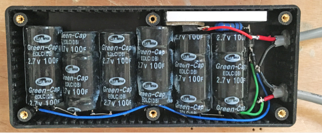
- 6 x 100F / 2.7V Supercapacitors, £13 from a seller on eBay. There are plenty of these, the ones I got were "Samwha Green Cap". I hadn't heard of Samwha, but they are a large Korean manufacturer and their parts are sold by Farnell. I wanted a reputable manufacturer for these.
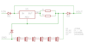
- 2 x 1Ω / 3W Metal Oxide Resistors
- 1 x LM350, to limit the charging current for the capacitors
- 2 x 1N5408 Diodes
- 1 x 15V Zener to keep the capacitors below 2.5V
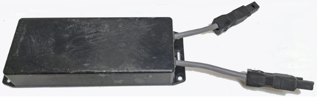
- 1 x Box to put them in
- 50mm or so of 25mm wide aluminium heatsink, stuck to the LM350 with a thermal pad. Both items usually used to heatsink LEDs, you'll find them on eBay. Without this the LM350 will overheat and shut down.
No fancy circuit board for this one: I stuck the caps together with contact glue, soldered everything together with short wire segment and stuck it all in the box with a dab of glue under the caps holding it all in place. The box fit like a glove.
The capacitors will charge to the battery level less 0.6V for the diode drop. Just in case they're limited to 2.5 each by the 15V Zener, as I believe I would regret overcharging a 100F electrolytic capacitor. With the diode drop from D1, it will only start conducting if the battery goes above about 15.6V (unlikely).
The charge rate is limited by the LM350 to the level set by the resistors, and I have set these to 0.5Ω to give 2.5A charge current (with this schematic, current = 1.2 / R)
The discharge current from these capacitors, and the current through the UPS (i.e. directly from Vin to Vout) is unlimited - this is important, as I don't want to choke the supply to the computer: my reason for limiting the current is to prevent a sudden inrush into the capacitors from tripping the fuse. The second diode introduces another 0.6V drop. Maybe there's a way to do all of this with one diode, but after half an hour trying to figure it out I decided it didn't matter: I'm stepping the voltage down to 5V everywhere anyway, so all it will cost me is a few seconds runtime.
The whole thing works very well, and the 600mA or so my computer and accessories are drawing (at 12V) will run for about a minute before powering down: long enough to reflash the battery firmware or move a plug.