
Program an ATTiny45 with a Teensy 2.0
Categories
Tags
Recent articles
Ubuntu 16.10 LXC host on ZFS Root, with EFI and Time Machine
How to connect any serial device to the internet
I have a Teensy 2.0 and some ATtiny45 and ATtiny85 chips from Atmel, which I want to program with a minimum of fuss and parts. For me this means using the Teensy as an "In System Programmer" or ISP, and there are plenty of other articles on how to do this. But I thought I'd file what I've got here for reference anyway.
It's very easy - no hardware required except a Teensy, the ATTiny, a breadboard and 4 wires, and for software I started with the Arduino 1.0 environment with the Teensyduino additions - just what you'd normally need to upload sketches to the Teensy. Here's what I did.
- Download and install the ATTiny cores for the Arduino IDE (for now I'm using the IDE, I'll update this when I switch to make and avrdude). There are a quite a few different cores developed by different people and they're not all equal, which is not obvious when you start this process. I picked the ones from the above repository.
- Open the Arduino IDE and plug in the Teensy 2.0. Select the "Arduino ISP" from the File/Examples menu and change the #define for LED_HB to 11. This will blink the orange light on the Teensy when the programmer is running. Then upload the sketch to the Teensy.
- On a breadboard, wire these pins together:
- Teensy 2.0 pin B0 <-> ATTiny45 pin 1
- Teensy 2.0 pin B1 <-> ATTiny45 pin 7
- Teensy 2.0 pin B2 <-> ATTiny45 pin 5
- Teensy 2.0 pin B3 <-> ATTiny45 pin 6
- ... and connect 5V to ATTiny45 pin 8 and GND to Attiny45 pin 4
- In the Arduino IDE, under the Tools menu change the "Programmer" to "Arduino as ISP" and the "Board" to "ATTiny45 @ 1Mhz". Then load your sketch for the ATTiny and upload as before. For testing I used the "Blinky" example and changed the pin to 4. It should upload with a couple of "Please define PAGEL and BS2 signals in the configuration file for part ATtiny45" warnings, which you can ignore
- If you'd prefer to program directly from avrdude, the command should look something
like:
avrdude -c avrisp -P <strong>/dev/tty.usbmodem12341</strong> \
   -p <strong>attiny45</strong> -U flash:w:<strong>main.hex</strong>:i
where:
- /dev/tty.usbmodem12341 is the USB port the Teensy is plugged into
- attiny45 is the type of AVR chip you're programming
- main.hex is the hex file you have compiled and built with avr-gcc and avr-objcopy
That's it, really, and it's all ground that's been covered before.
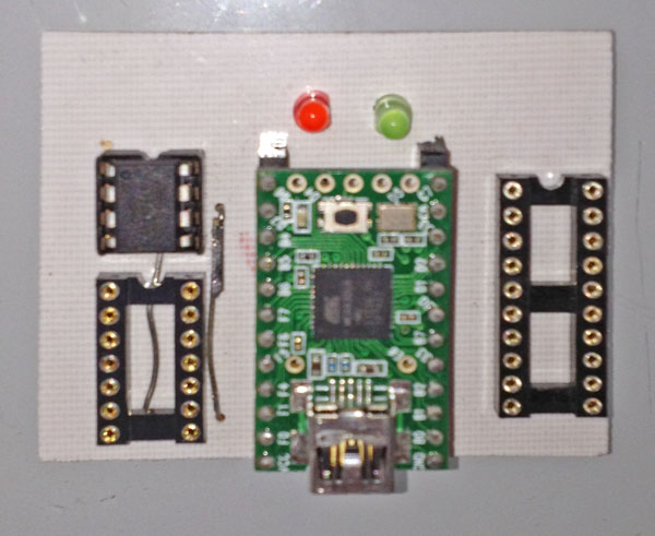
If you're going to do this a bit then it's worth getting it off the breadboard, so I rustled up a quick circuit in Eagle (which you can download). It has sockets for programming 8, 14 or 20 pin ATTiny chips, plus a couple of LEDs to indicate error (red) and communicating with the ATTiny (green), and you can see a photo at the top of this blog. You'll need the following parts:
- 1 x 8 pin socket
- 1 x 14 pin socket
- 1 x 20 pin socket
- 2 x 22 pin PCB connector
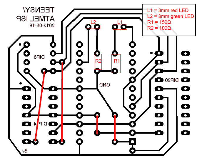
- A red and green 3mm LED, a 100Ω and 150Ωresistor and some short lengths of wire to connect hard-to-route points on the top of the board. The location for these parts are marked in red.
The download contains the circuit as a PNG for etching (make sure you etch so the text is the right way around) plus the source for a slightly modified version of ArduinoISP which I've called "TeensyISP.ino" - this has the correct #defines for the pins on the Teensy. Then just plug the Teensy into the PCB connectors in the middle of the board, put your ATTiny chip in the appropriate socket and upload as described above. Easy.
Incidentally, with a cost of about $16 for the Teensy plus maybe $2 for the LEDs and sockets, this is also probably the cheapest way to build an ISP programmer.
Update August 2013
 I have switch to SMD / SOIC chips for almost all my projects, and the rig to connect
the clip to the
programmer described on this page is flakey at best. I also realise that the most
flexible way to
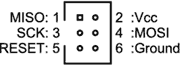
do this is to use the standard 6-pin interface and put a headers to connect the cable
on each
board I design. This allows you to program any ATtiny or ATmega chip, and is a good
idea for all but
the smallest boards.
I have switch to SMD / SOIC chips for almost all my projects, and the rig to connect
the clip to the
programmer described on this page is flakey at best. I also realise that the most
flexible way to
do this is to use the standard 6-pin interface and put a headers to connect the cable
on each
board I design. This allows you to program any ATtiny or ATmega chip, and is a good
idea for all but
the smallest boards.
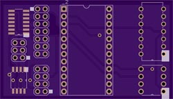 Finally, I discovered OSHPark which is cheap enough that I'll never
have to burn another circuit board again! This fills me with indescribable joy. So
here's the board I use,
which is the same circuit as above, minus the LEDs. It has sockets for the 8 and 16
pin chips I use a
lot of, SOIC pads for the same, plus 8/16 pin headers for the programming clip. Finally
it has a 6-pin
header for a standard programming cable.
Finally, I discovered OSHPark which is cheap enough that I'll never
have to burn another circuit board again! This fills me with indescribable joy. So
here's the board I use,
which is the same circuit as above, minus the LEDs. It has sockets for the 8 and 16
pin chips I use a
lot of, SOIC pads for the same, plus 8/16 pin headers for the programming clip. Finally
it has a 6-pin
header for a standard programming cable.
Download the Eagle files here.